
Features
Animated 3D visualization
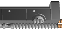
Every change to a screw & barrel configuration is online visualized in a 3D model on the screen. The model can even be animated to rotate the screws.
CAD Drawing
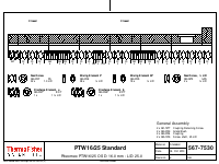
As an output ScrewConfig creates a CAD drawing to document the configuration. This drawing is used as an instruction how to assemble the configuration and can be stored to document the configuration in a secured mode (as pdf).
Screw Element Palette
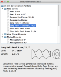
The Screw Element Palette dialog contains all screw elements available for the currently edited extruder. A description text explains the purpose of various screw element types and explains their properties.
To build a screw configuration, the elements can be draged from the element dialog.
Wizard dialogs
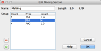
Wizard dialogs allow defining the screw sections on a more abstract level.
The user just defines the length of the section (eventually with sub sections) and the ScrewConfig software takes care about selecting and placing the correct screw elements. This is very effective especially for novices to screw configurations.
Revision tracking
Every modification the user applies to a configuration automatically generates a new revision. This revision is displayed on the drawing next to the user's name and the date the modification was done.
